
电 话:021-39526589
网址:www.qiant.net
地 址:上海嘉定区嘉涌路99弄6号楼713室
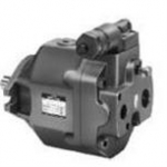
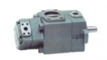
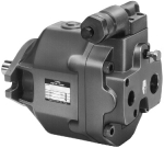
日本YUKEN进给控制阀技术样本
上海乾拓贸易有限公司
联系人:杨江玲
企业QQ:2880626083
手 机:18917074297(微信)
电 话:021-39529830-8012
邮箱;18917074297@163.com
地址:上海市嘉定区江桥嘉涌路6号楼713室
in the installation drawings. Allowable drain port back pressure Limit to 0.1 MPa (15 PSI).
Japanese Std. "JIS" & European Design Std. N. American Design Std.
UCF1G-01 UCF1G-03 UCF2G-03 UCF1G-04 UCF2G-04
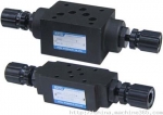
These valves are the combination of flow control valve, a deceleration valve
the hydraulic fluids which may otherwise l ead to breakdowns and shorten the life of the valves.
Recommended Viscosity and Oil Temperatures 2 Viscosity ranging between 15 - 400 mm /s
(77 - 1800 SSU). Oil temperatures between -15/+70°C (5 - 158°F).
Use hydraulic fluids which satisfy the recommended viscosity and oil temperatures given above.
Use fluids equivalent to ISO VG 32 or VG 46. Use phosphate ester or polyol ester fluid.
When phosphate ester fluid is used, prefix "F-" to the model number because the special seals
(fluororubber) are required to be used. Use water-glycol fluid.
M6 × 55 Lg. M6 × 55 Lg. M6 × 55 Lg. M10 × 70 Lg. M10 × 70 Lg.
and fine feed control is accomplished by dial rotation regardless of pressure
and oil temperature variation. Rapid return is free of cam actuation.
Fluid Types Any type of hydraulic fluids listed in the table below can be used.
Please maintain the degree of contamination within NAS 1 638-Grade 12. Use 25 µm or finer line filter.
1/4-20 UNC × 2-1/4 Lg. 1/4-20 UNC × 2-1/4 Lg. 1/4-20 UNC × 2-1/4 Lg.
and a check valve and used mainly for controlling rapid traverse and feed cycles machine tools.
Switching from rapid traverse to feed is made by a cam operation,
Note:For use with hydraulic fluids other than those listed above,please consult your Yuken representatives in advance.
Attachment Mounting Bolts
3/8-16 UNC × 2-3/4 Lg. 3/8-16 UNC × 2-3/4 Lg.
Allowable pressures at controlled flow outlet If internal drain types of UCF1G-01
Spool push down level Limit the spool push down level within the allowable maximum stroke range shown
In addition, connect the drain pipe independently and directly to the tank.
(This applies only to external drain types.)
Control of Contamination Due caution must be paid to maintaining control over contamination of
or 03 or UCF2G-03 a re used, use them in metre-out circuits in order to limit the valve outlet
pressure to the valves shown below. In addition, external drain types can also be used in metre-in circuits.
Minimum required pressure difference The minimum pressure differential between inlet
and outlet port is required to obtain the optimum pressure compensation.
It varies accordingly to the flow rate to be s et. For details, refer to the performance curve.
日本YUKEN进给控制阀技术样本
021-39526589
网址:www.qiant.net
地 址:上海市嘉定区嘉涌路99弄
6号楼713室


 旺旺
旺旺